
Paper published by IE for their 32nd Engineering Congress- Chennai
32nd
Indian Engineering
Congress, The Institution of Engineers (India)
Chennai,
2017
Theme: Innovation in Engineering:
Competitive Strategy Perspective
|
Evolution of Automatic Gauge
Control philosophy for flat rolling in Single Stand Mills.
Amitabh Kumar Sinha, B.Sc (Engg), FIE, Ranchi,
India, amit1950@yahoo.co.in
|
Abstract
During the course of author’s working in Steel Industry,
world of automatic gauge control changed from Mechanical Screw Down Control to
Hydraulic AGC. This led to evolution of different control philosophies
depending upon available sensors, required and possible response time as well
as customer expectations and quality concerns. The control system also changed
from available sophistication in automation e.g. from operational amplifiers
and potted logic blocks of 70’s to Micro Processor and PLC based system
including higher levels of process controls. The paper sums up the control strategies
used from 1970’s till now for single stand steel mills, though some old methods
may be still prevalent due to other considerations such as cost. The present
study ignores effect of rolling speed, roll deformation, roll coolant etc on
AGC.
Initially mechanical screw down with large size DC
motors were used for AGC control with a selsyn or pulse encoder as position
sensor and load cells as roll force sensors. Basic parameter for control was
back tension which was a fastest controlled parameter at that time. Roll gap
was changed only if permitted change in back tension was not sufficient to get
a desired thickness control. Once hydraulic roll cylinders were available for
Automatic Gauge Controls, the scenario changed from tension control to direct
roll gap control since faster control of cylinder position was possible. With
improvement of Gauge measurement and other sensors and advent of
micro-processors and PLC the control philosophy constantly changed and
methodology of mass flow were also used. In multi stand mills one stand was
used as reference mill and other stands will have speeds as per reduction in
each stand since speed ratio will correspond to thickness reduction as per
constant mass flow. For constant mass flow, hinv1=houtv2, i.e. hout = hinv1/v2,
for a given constant. These principles are explained in the following articles
in some detail with electro mechanical explanations as per authors’ experience
in design and commissioning of such mills.
Keywords: AGC, Mass Flow, Screw
Down, Mills
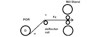
AGC through control of Back Tension
Before Hydraulic AGC
Cylinders became a standard fixture in flat rolling mills, electrical DC motors
were used to adjust top rolls for roll gap adjustment. Different systems from
Ward Leonard to SCR’s controlled bridge rectifiers1 with or without circulating
current were used to fasten the response of screw down motor controls. However considering the slow response of such
motorized screw downs roll gap adjustment was used only as coarse adjustment
and alternative method was needed for fine gauge control. The fastest means was
to control the back tension. Rolling tension moves the neutral plane of rolling
forward or backward and thus changes the specific rolling pressure. This
reduces rolling force for same reduction of the strip. Tension
Fz changes the roll force needed for same reduction in following manner (simplified
formulae) :
Pm=Pm1 {1-(α0+ α1)/k}
……… (1)2
Where Pm
= specific rolling pressure, Pm1 =mean specific pressure with zero tension, α0
& α1 are entry and exit stress due to tension on the strip in kg/mm2 for a given reduction, k= A constant.
This
leads to following equation
Ra= Rf(1-k1*Fz) ………………. (1a)4
Where Ra
is actual roll force, Rf is roll force for same reduction with tension zero and
k1 is a multiplication factor.
Now we
know that
t2= s+Ra/mm
t2= s+Ra/mm
( ie loaded gap = no load gap+ mill stretch)- Gage
meter principle3
Where
t2= output thickness, s= unloaded gap in the mill and mm= mill modulus.
Thus
replacing Ra from first equation we get:
t2=s+(Rf*(1-k1*Fz))/mm ………(2)
Thus
first fixing a calculated roll gap then manipulating back tension Fz as required
up to a set limit for fine control, and then changing roll gap as coarse
control allowing some more correction in Fz fast gauge control was achieved.
Earlier
tension control of Pay off reel or tension reel was controlled using field
control of DC motor since SCR for armature control of such powerful motors were
not available then. This type of tension control was known as “Tension Control”
as opposed to torque control now applied. This control works with following
principle:
 |
| Fig-1 |
ϑ= π*D*n ie D= ϑ/π/n............................. (3)
Since T ά ф*Ia ie T ά If*Ia .........................(5)
Where Ia = motor armature current and If = motor field current. (фάIf)
Putting value of T from (4) to (5)
we have Fz= 2*k2*Ia*If/D where k2 is a constant. ................(6)
For
field
control n ά 1/ ф and ф ά If where ф =
Field Flux, ie n = k3/If…. (7)
=
Field Flux, ie n = k3/If…. (7)
where k3 is a constant.
For
a given fixed mill speed ϑ D*n = D*k3/If
Hence if If/D is
kept constant as per (6) Fz ά Ia………………(8)
For
keeping tension to a set value the motor has to run in constant power mode,
where entire motor control is in field weakening range – keeping motor voltage
constant. Base speed of motor is available at max OD of the coil and top speed
at the ID of the coil. Motor current is adjusted as per tension required. We
know motor power is proportional to tension x mill speed, Hence keeping motor
power constant results in constant tension and if motor voltage is constant
this means keeping motor current constant.
The above calculations and control block diagram are
shown in the graph below (fig-2).

 |
| Fig-2 |
AGC through calculated Roll Gap:
During late 70’s after hydraulic AGC were introduced
and became popular the faster controls directly of roll gap became possible and
full dependence on tension control was not needed. However measuring out going
thickness was not very fast and was not predictable accurately when material
was in bite. This led to using the calculated roll gap for control of thickness
using roll position control, roll force control & mill modulus to generate
the calculated loaded roll gap and hence output gauge. Finer roll gap
correction was done using feedback from X-Ray or isotope type thickness. Gauge
Difference from set value was corrected using faster AGC position control and
more accurate gap measurement using LVDT, relative and absolute position
sensors or other position sensors. Use of hydraulic AGC cylinders with position
sensors called for a procedure named calibration of the mill and position
controller. This was required since the top level of
bottom roll changed from campaign to campaign due to various factors including
roll turn downs.
Calibration
of position control:
In this write up I assume that mechanical screw down
for moving the rolls to compensate for roll turn downs for keeping pass
line, are mounted at the top of the mill
where as hydraulic cylinders are mounted in the bottom. Process as per author’s
experience is given below:
ii)
Bottom
rolls are lifted under roll force mode with kissing roll force reference
differential roll force reference as zero.
iii)
Rolls
will rise to touch to top rolls and touch either on drive or operator side as
per skew due to error in parallel position of top rolls.
iv) Roll force will develop and rise up to
the set value. Differential roll force also will rise since the rolls touches
only on one side. Differential roll force controller comes into action to
achieve the set value of zero, thus ensuring the rolls touch both side with
equal force.
v)
The
above roll position is registered as kissing position or unloaded zero gap
position. Rolls are rotated at small speed.
vi)
Total
roll force is then raised to another set value called the calibration roll
force.
vii)
Though
the rolls are still touching but position sensors will read another position
due to mill stretch and this is also registered. The difference in the two
registered position divided by roll force gives mill stretch coefficient ie
mill modulus “mm”
viii) Mill calibrated signal lights up.
 |
| Fig-3 |
Mass Flow
Principle
With the advent of faster non-contact thickness
gauges, AGC suppliers introduced a another method of measuring loaded roll gap
or output thickness by using a simple principle that mass remains constant.
Thus if entry side thickness is hin
and entry material
speed is ϑ1 , exit
side thickness is hout and exit side material speed is ϑ2 then considering that there is no change in
width of material,
hin *ϑ1= hout ϑ2 thus hout= hin *ϑ1/ ϑ2…………………………………… (9)
Thus if we are able to measure entry and output
material linear speed and entry side thickness we have quite accurate and fast
value for exit thickness, thus accurate AGC was possible with this calculated
output thickness with over all vernier correction from exit thickness gauge. See
figure-4.

 |
| Fig-4 |
 |
| Fig-5 |
Null Setting for Moog Servo
Valves:
In the various mill stands commissioned by the
author Moog Servo Valve of 72 series are used for control of Hydraulic Force
Cylinders. These valves have certain amount of flow even with zero control
current. This flow will either make to top and bottom roll come together or
separate from each other and may move with a skew (unparallel movement) when
the power to the Moog Valves are powered off. If the rolls do come together the
chance is that they will move and raise the roll force to unsafe values. Hence
to have safe operation it is imperative that top and bottom rolls move away
from each other with near equal speed or in parallel motion. The Moog Valve are
provided with a “Null flow screw” and the manufacturer has provided 25
methods to adjust in the catalogue n namely mechanical and electro-magnetic.
Author did come across a much simpler procedure which however needed the
position control commissioned and working. The procedure is very simple where
in the rolls are separated to a fixed gap and the control system will keep the
rolls at this gap – not affected by the null flow. Now the null screws on both
drive side and operator side servo valves are adjusted one by one such that
direction of control current is for same as for gap “closing” and is 2-4 % of
full flow. Care is taken that this null current is same for both operator and
drive side. Thus once the power is off the roll gap will “open” with almost
parallel movement of rolls.
Conclusion:
With the use of Hydraulic AGC cylinders and fast and
accurate position sensors and thickness gauge Automatic Gauge Control for flat
mills have undergone sea change from controls through back tension to actual
position. Temper passing in Cold Mill with constant roll force has also become
feasible. In India Hydraulic AGC were introduced in late seventies and now is a
standard fixture in flat rolling mills.
Acknowledgement
/ Bibliography
1) G.Molten,
Line Commuted Thyristor Convertors, Siemens Ag, 1972
2) A.Teliskov,
Stress and Strain in Metal Rolling. Mir Publishers, Moscow, 1967.
3) Peter Kucsera & Zsolt Béres, Hot Rolling
Mill Hydraulic Gap.., Published in Acta Polytechnica Hungarica, Vol 12 No 6,
2015,
4) William
L Roberts, Cold Rolling of Steel, 1978
5) Moog
Servo Valve 72 series Technical Catalogue Rev-2, 2013

Comments
Post a Comment